
INSTRUCTIONS
WARNING!
Always inspect your equipment prior to shooting an arrow. Before
you take a shot, know your target and what lies beyond your
target for safety purposes.
You are responsible for understanding and complying with any
applicable regulations for shooting a bow and arrow.
See the Important Safety and Product Information guide in the
product box for product warnings and other important information.
Removing the sensor will damage the strain gauges and render
them useless. BE SURE TO THOROUGHLY READ INSTRUCTIONS
AND WATCH VIDEO BEFORE ATTEMPTING TO MOUNT
YOUR SENSOR.
Mounting the sensor card incorrectly will VOID your warranty
on the sensor. If you damage your sensor you can purchase
a replacement.
Installation of Sensor
(THIS IS THE MOST CRUCIAL PART OF INSTALLING
SWEETSPOT. IF THE SENSOR IS NOT ADHERED CORRECTLY
THE SYSTEM WILL NOT BE RELIABLE.) PLEASE WATCH THE
YOUTUBE VIDEO ON SECURING YOUR SWEETSPOT SENSOR.
YOU ONLY GET ONE CHANCE AT THIS!
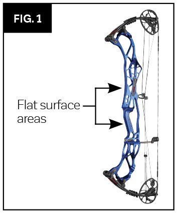
Step 1)
Pick a mounting location – IT MUST BE
on the front of the bow,
facing the target and be flat and large
enough for the sensor to fit comfortably.
On most bows, this will be the grip.
For some, it may be higher on the riser
between the shelf and the sight. (See
Fig. 1)
Step 2)
Clean the area thoroughly with an alcohol pad where the sensor will be mounted.
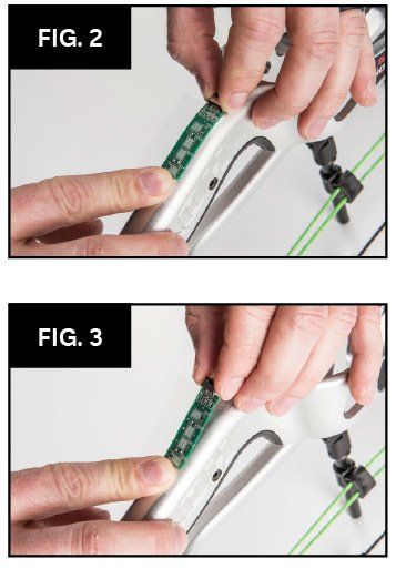
Step 3) Apply a piece of scotch tape to
the top of the sensor hanging over so
that it can be stuck straight and square
on the front of the bow
(see Fig. 2).
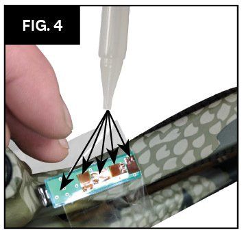
Push the tape down to act as a hinge so
the sensor can fold back away from the
bow (to allow glue to be applied to the
sensors in step 3)
(See Fig. 3).
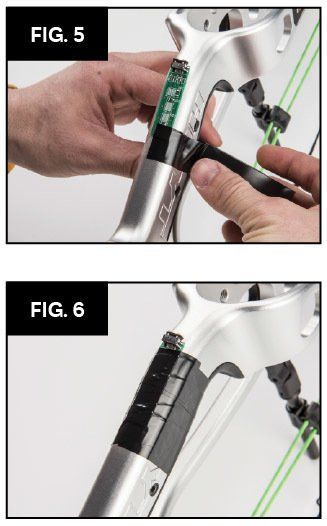
Step 4)
After double checking the sensor is square and does not
protrude over the edge of the riser. Fold the sensor back so the
4 copper strain gauges are facing up towards you. Apply a dot of
glue on each copper pad (dot should be the same size as the copper pad). Cover the green pc board above the strain gauge with glue. Tip:
more glue is better than
not enough glue. (See Fig. 4).
Step 5)
Starting at the bottom where
the tape meets the edge of the green
PC board, rotate the sensor towards
the bow making sure to keep it straight.
Make sure not to let the sensor slide.
Press and hold the sensor down evenly and firmly for 15
seconds. Be careful when you pull your fingers off not to let
glue stick to them and pull the sensor off. Push the tape down
completely around the sensor.
Step 6)
Use electrical tape to go around the sensor and the riser.
Lightly at first to be sure the sensor does not slide. Once you
have two full wraps around the sensor, pull the tape snug going
around the sensor from bottom to top to the USB connector.
This forces out any air bubbles and keeps the sensor secure while it cures (this tape can be removed in 24hrs after the glue has completely cured) (see Fig. 4).
Once you reach the USB connector cut off the excess tape with scissors. This will apply even pressure to the sensor. Leave the electrical tape on and allow the glue to cure for a MINIMUM
of 4 hours (see Fig. 5).
Step 7)
After 24 hours you can plug in the micro USB cable from the SweetSpot being careful to have it turned the correct way. It does not take much force to plug in the cable. If it is difficult, double-check that it is lined up correctly.
Step 8)
If you wish to remove the electrical tape, wait 24 hours. It is recommended to leave the tape on to protect the sensor (see Fig. 5).
It is also highly recommended, after the cable is plugged into the sensor, to wrap the sensor with grip tape for extra insulation so temperature will not have an adverse affect on it.
Step 9)
Route the cable, being sure to avoid any moving parts (cable slide, arrow, arrow rest, sight) up to the where you will mount the SweetSpot, securing it with supplied zip ties. There should be a zip tie 1-2 inches from the sensor to secure the cable to the bow and prevent the cable from being snagged.
Mounting the SweetSpot, LED card and
plugging in cables
• Use the supplied Velcro strips to secure the SweetSpot
controller to your sight rod or bow riser. Be sure the cable from the sensor will reach the sensor port without damaging the wire.
• Once the SweetSpot is secured to the bow, plug the other end of the micro USB cable (from the sensor) into to the port labeled (sensor) on the SweetSpot. It is important to have strain relief loop on all cables before you plug them into the SweetSpot. This will prevent excess vibration from damaging the sensor and LED ports when the bow is fired. (We are not responsible for any misuse or incorrect installation
resulting in damaged products or injuries to one’s self
or a bystander.)
• Take your time to determine a location to mount the LED card. Remember you want to be able to see this at full draw to reap the benefits of the system (this is personal preference, but most prefer to mount the LED card inside the scope housing. Some scope setups allow you to mount the LED card directly behind the level, which will brighten the level green or red and helps to see your bubble in dark conditions. Depending on your field of view through your peep sight, you may be able to mount the LED card on top of your scope housing). Be sure the location you choose will not affect the flight of your arrow.
• Once you have selected a safe and efficient location that
you can see at full draw, clean the surface with an alcohol prep pad.
• Peel off the double-sided tape from the LED card and press the LED card down carefully, so as not to break the traces. You can form the LED card to fit the radius of your scope. Be sure to only bend the card slightly and only in one direction. If you bend it in one direction it CANNOT bend the other direction without damaging the card. If the LED card is bent repeatedly, it will break the traces and the LED’s will not work. If you choose to use the lighted pin option when using a fiber optic to aim, route the wires around the scope housing to your fiber. If you are not using a fiber optic to aim, simply unplug the white PicoBlade connector carefully, using tweezers or holding each end, and set aside for later use.
• Plug in the micro USB connector from the LED card you just installed into the port on the SweetSpot labeled (LED) and secure the cable with supplied zip ties. Be sure to put a strain relief loop in the usb cord before plugging it in. This will require a zip tie or tape a few inches back from the connector so that the cable is secure and then loose for 2 inches to the port. This allows vibration to be soaked up before it is directed into the port.
Using the SweetSpot
• Use the supplied Velcro strips to secure the SweetSpot
controller to your sight rod or bow riser. Be sure the cable from the sensor will reach the sensor port without damaging the wire.
• Once everything is mounted, secured and plugged into the correct ports on the SweetSpot. BE SURE to check and make sure no wires interfere with any moving parts and will not interfere with the arrow leaving the bow. (Pressure Perfect Products is not responsible for misuse or improper installation.)
• Go to http://sweetspotarchery.com/installation for
installation and instructional videos.
SweetSpot PRO Software
Definitions
• Press: Press button down briefly then release
• Hold:
Press button down and hold
Buttons from Left to Right
• [Power]:
Turn device ON or OFF
• [Left]:
Menu navigation and decrement values
• [Select]:
Select/apply settings
• [Right]:
Menu navigation and increment values
Menus
• ACTIVE:
Shows current force count of bow
• OPT VALUE:
Set optimum count threshold • HIGH VALUE:
Set high count threshold
• CALIBRATE/TARE:
This zeros the bow for your current conditions (uphill, downhill, temperature change, stabilizer or any change to strings or cables). Like a weight scale, whatever this is off at static will be off at full draw.
• SHOTS FIRE:
Review shots fired
• SHOT COUNT:
Count of shots fired
• SHOT TIMER:
Shot time alarm
• BRIGHTNESS PIN:
Brightness setting for pin LED
• BRIGHTNESS OTHER:
Brightness setting for other LEDs
• TEMP COMP:
This is resolved by calibrating
• WIFI:
WIFI toggles from AP mode to coaches mode
• PASSWORD:
WIFI password
• DATETIME:
Current date and time
• VERSION:
Software version
Setup
Upon the first power-up or a factory reset, the device will need to be calibrated. See the Section Hard Calibration
below to calibrate the device.
After calibration, the Optimal
and High
values will be automatically set. See the Section Optimal Value
and High Value
below for instructions to manually adjust the Optimal
and High
values respectively.
Hard Calibration
Use the <CALIBRATE>
menu to perform a hard
calibration upon first power-up, after a factory-reset, or after physical changes to do a reset. While device is off, hold up and down and press power. Continue holding until reset done. This deletes all shots but needs to be done if replacing sensor or changing bows:
• Navigate to <CALIBRATE>
• Relax the bow strings and keep steady
• Hold [Select]
until the display changes
• Wait until the display shows “Fire Shot”
• Shoot an arrow as you normally would
• The <ACTIVE>
screen should be shown
Soft Calibration/Tare
This zeros the bow for current conditions, weather/equipment change etc. This does not delete any settings and only zeros the bow. If the active screen is off more than +5 or -5, it is important to calibrate/tare. Like a weight scale, whatever this value is off at static will be off at full draw. You must hold the bow exactly the same each time you calibrate. Use the <CALIBRATE>
menu to perform a soft calibration when the force counts drift:
• Navigate to <CALIBRATE>
• Relax the bow strings and keep steady
• Press [Select]
• Wait until the <ACTIVE>
screen is shown
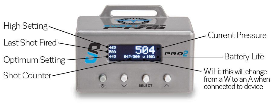
Active Screen
After a calibration, the <ACTIVE>
screen will show.
• Force counts
• High counts
• Last shot counts
• Optimal counts
• Number of shots recorded
• Maximum number of shots
• WIFI enabled
(disabled if not present)
• Battery percentage
Optimal Value
• Navigate to <OPT VALUE>
• Press [Select]
to begin adjustment
• Press [Left]
or [Right]
to decrement or increment respectively
• Hold [Left]
or [Right]
to repeatedly decrement or increment respectively
• Press [Select]
to apply
High Value
• Navigate to <HIGH VALUE>
• Press [Select]
to begin adjustment
• Press [Left]
or [Right]
to decrement or increment respectively
• Hold [Left]
or [Right]
to repeatedly decrement or increment respectively
• Press [Select]
to apply
Shots Fire
Use the <SHOTS FIRE>
menu to view past shots:
• Navigate to <SHOTS FIRE>
• Press [Select]
to begin viewing
• Press [Left]
or [Right]
scroll through past shots
• Hold [Left]
or [Right]
scroll through past shots faster
• Press [Select]
to end viewing
• Use the <SHOTS FIRE>
menu to clear all shots:
• Navigate to <SHOTS FIRE>
• Hold [Select]
until the numbers display “0: 0”
Shot Count
Use the <SHOT COUNT>
menu to view the total number of shots fired since factory-reset or since reset of the counter. To reset the counter:
• Navigate to <SHOTS FIRE>
• Hold [Select]
until the numbers display “0”
Shot Timer
Use the <SHOT TIMER>
menu to set the alarm time in seconds to flash both LEDs:
• Navigate to <SHOT TIMER>
• Press [Select]
to begin adjustment
• Press [Left]
or [Right]
to decrement or increment respectively
• Hold [Left]
or [Right]
to repeatedly decrement or increment respectively
• Press [Select]
to apply
Pin Brightness
Use the <BRIGHTNESS PIN>
menu to set the brightness of the Pin LED:
• Navigate to <BRIGHTNESS PIN>
• Press [Select]
to begin adjustment
• Press [Left]
or [Right]
to decrement or increment respectively
• Hold [Left]
or [Right]
to repeatedly decrement or increment respectively
• Press [Select]
to apply
Optimal and High LED Brightness
Use the <BRIGHTNESS OTHER>
menu to set the brightness of the Pin LED:
• Navigate to <BRIGHTNESS OTHER>
• Press [Select]
to begin adjustment
• Press [Left]
or [Right]
to decrement or increment respectively
• Hold [Left]
or [Right]
to repeatedly decrement or increment respectively
• Press [Select]
to apply
WIFI Modes
Use the <WIFI>
menu to switch the mode between
• AP: The device behaves like an Access Point and creates a private network
• Use the SSID shown to connect to the device
• Use the password shown on the <PASSWORD>
menu
STA: The device connects to a WIFI Router. Most commonly used for public access.
• See Section Settings Page
for router setup
• OFF: The WIFI is turned off to save battery life.
• Navigate to <WIFI>
• Press [Select]
to switch modes
To generate a new AP SSID:
Navigate to <WIFI>
• Press [Select]
to switch mode to AP, if not already in that mode
• Hold [Select]
until the SSID changes
WIFI Password
Use the <PASSWORD>
menu to view the password to access WIFI in AP
mode.
• Set WIFI mode to AP
• Navigate to <PASSWORD>
• Use password to connect to device
To generate a new AP
Password:
• Navigate to <WIFI>
• Press [Select]
to switch mode to AP, if not already in
that mode
• Navigate to <PASSWORD>
• Hold [Select]
until the Password changes
WIFI Connection
The device has a built-in webserver. Follow these steps to access the homepage:
• Navigate to <WIFI>
• Press [Select]
to switch mode to AP, if necessary
• Note the SSID
shown
• Navigate to <PASSWORD>
• Note the Password
shown
• Use the SSID and Password
to connect to the WIFI
• Open the homepage 10.0.0.1
in an internet browser
Note: The device’s date and time is automatically synced to your computer/phone when you open the homepage link above. If your device says “no internet”, press dismiss. To connect via WIFI, you do NOT need internet access or a router to do so. This works exactly like bluetooth but reaches farther and is more secure.
Date and Time
The date and time might not be correct upon the first power-up. To sync the date and time to the computer, follow the steps in the Section WIFI Connection to open the homepage.
The time can be shown in 24-hour or 12-hour format:
• Navigate to <DATETIME>
• Press [Select]
to switch between 24-hour and 12-hour format
Webserver
The built-in webserver has the following functions:
• View and Save past shots
• View real-time force
• Configure settings
To connect to the webserver, see Section WIFI Connection. On the webserver, you can see more about your shot by clicking “5 sec.” on the bottom of the page. This shows you the last 5 seconds before you fired – if you were adding pressure, creeping or maintaining before you fired. You will also see how well you’re holding as the sensor is sensitive enough that the movement will introduce more flex to the riser.
Factory Reset
• Power off device
• Hold [Left]
and [Right]
while Pressing [Power]
• Wait until “Reset Done”
is displayed
• Release Buttons
Note: The WIFI SSID, password, and channel do not get reset on a factory-reset.